
The LM5104 is a high voltage half-bridge gate driver designed to drive both the high side and low side N-Channel MOSFETs in a synchronous buck configuration. It features adaptive transition timing to prevent shoot-through issues. Additionally, it allows for an additional delay time to be added using an external setting resistor. The device also includes an integrated high voltage diode for charging the high side gate drive bootstrap capacitor. It operates at high speed with low power consumption and provides clean level transitions. The LM5104 is suitable for applications such as current fed push-pull power converters, high voltage buck regulators, and active clamp functions.
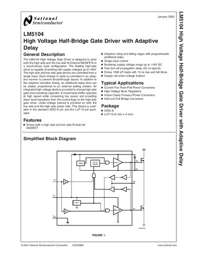
The LM5104 is a high‑voltage half‑bridge gate driver designed for synchronous buck and half‑bridge converters. It drives both high‑side and low‑side N‑channel MOSFETs from a single PWM input and includes adaptive delay and programmable dead‑time to prevent shoot‑through.
The document contains a general description, features, typical applications, package options, pin‑out tables, absolute maximum ratings, electrical characteristics, performance graphs, timing diagrams, mechanical dimensions, land‑pattern recommendations, and compliance statements.
| Bootstrap supply voltage range | up to 118 V DC |
|---|---|
| Fast turn‑off propagation delay | 25 ns typical |
| Load drive capability | Drives 1000 pF loads with 15 ns rise/fall |
| Under‑voltage lockout | Provided on both high‑side and low‑side rails |
| Operating temperature range | -58 °C to +150 °C |
| Package options | SOIC‑8 and LLP‑10 |
The driver can operate with a bootstrap supply voltage up to 118 V DC and a high‑side supply voltage up to 100 V.
Dead‑time is set by an external resistor connected to the RT pin; the resistor value determines the delay.
The device is offered in SOIC‑8 and LLP‑10 (4 mm × 4 mm) packages.