
This document is about 50V, 100V, 500V, 1KV, 2KV temperature compensating ceramic disc capacitor specification
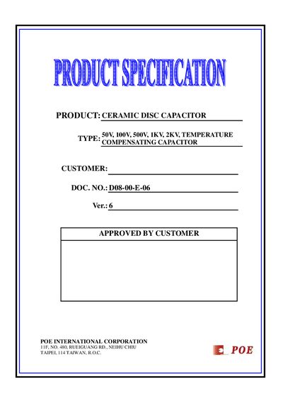
This document defines the test methods, performance limits and physical characteristics of POE temperature‑compensating ceramic disc capacitors. It applies to capacitors rated at 50 V, 100 V, 500 V, 1 kV and 2 kV and describes the required handling, testing and marking procedures.
Key sections include scope, test conditions, temperature coefficient calculations, capacitance tolerance, lead wire specifications, humidity and insulation resistance tests, and detailed lead style tables. The data is intended for design engineers and quality‑control personnel who need to verify compliance with POE’s specifications.
| Rated Voltage Options | 50 V, 100 V, 500 V, 1 kV, 2 kV |
|---|---|
| Operating Temperature Range | -25 °C to +85 °C |
| Temperature Coefficient (TC) | -150 ppm/°C to +160 ppm/°C (varies by class) |
| Insulation Resistance Minimum | 1000 MΩ |
| Lead Wire Diameter (low voltage) | 0.5 mm |
| Lead Wire Diameter (high voltage) | 0.6 mm |
| Capacitance Tolerance | ±0.296 pF to +0.5 pF depending on voltage class |
The standard test conditions are a temperature range of –25 °C to +35 °C (or up to +85 °C for some tests).
The specification requires a minimum insulation resistance of 1000 MΩ.
The capacitor must be kept at room temperature for at least 30 minutes and be completely discharged before testing.
Low‑voltage capacitors use a 0.5 mm diameter lead wire with a loading weight of 0.5 kg for a tensile strength of 10 seconds.