
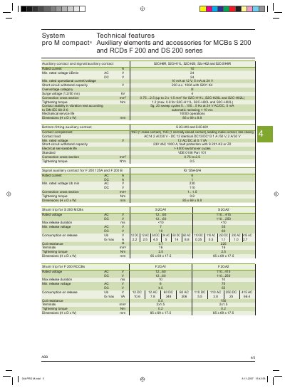
This document provides detailed technical data for the auxiliary elements and accessories compatible with ABB System pro M compact® MCBs (S 200 series) and RCCBs (F 200 and DS 200 series). It includes rated currents, voltage limits, mechanical dimensions, and installation requirements for each type of contact, shunt trip and auxiliary device.
The selection tables list part numbers, ordering codes and key parameters such as short‑circuit withstand capacity, connection cross‑section, tightening torque and mechanical service life. The information helps designers and installers choose the correct auxiliary component for a given protection device and application.
| Rated current | 10 A |
|---|---|
| Minimum rated voltage | 24 V AC / 24 V DC |
| Short‑circuit withstand capacity | 230 VAC 100 A |
| Connection cross‑section | 20.75 mm² … 2.5 mm² |
| Tightening torque | 1.2 Nm (max 0.8 Nm for certain types) |
| Mechanical service life | 10 000 operations |
| Dimensions (H × D × W) | 85 mm × 69 mm × 8.8 mm |
The rated current is 10 A.
They can withstand a short‑circuit current of 230 VAC 100 A.
The contacts measure 85 mm × 69 mm × 8.8 mm (H × D × W).
A tightening torque of 1.2 Nm is required, reduced to a maximum of 0.8 Nm for certain variants.