
This document describes the features and performance of Welwyn Components' ULW series resistors. These resistors have high power and thermal impedance performance, and can withstand high voltage and overload. They have a wide resistance range and good temperature coefficient and isolation voltage. Additionally, these resistors are UL recognized and have fusible functionality.
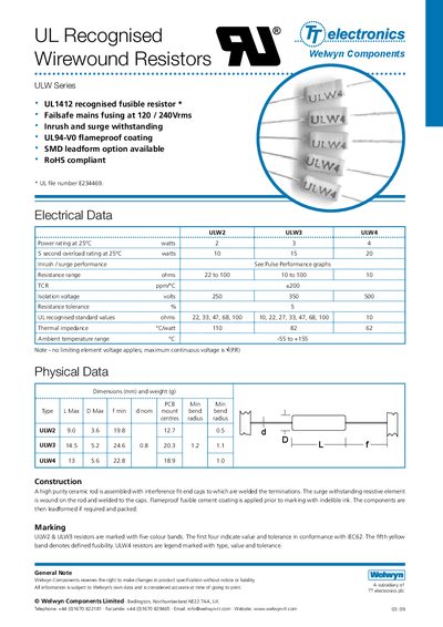
The ULW Series from Welwyn Components comprises UL‑recognised fusible wirewound resistors (ULW2, ULW3, ULW4) designed for high‑reliability applications. They feature a high‑purity ceramic rod, interference‑fit end caps, flame‑proof coating, and optional SMD lead‑form.
The sheet lists detailed electrical data (resistance range, TCR, isolation voltage, tolerance), physical dimensions, thermal performance, pulse and fusing characteristics, as well as application guidelines such as minimum clearance from combustible materials and termination placement. Packaging options and ordering procedures are also included.
| Resistance range | 22 Ω to 100 Ω |
|---|---|
| Temperature coefficient (TCR) | +200 ppm/°C |
| Isolation voltage | 250 V / 350 V / 500 V |
| Resistance tolerance | ±5 % |
| Thermal impedance (ULW2) | 110 °C·W |
| Ambient temperature range | -55 °C to +155 °C |
| Pulse energy limit | 1.2 J per 50 µs pulse |
| Peak voltage limit (ULW4‑10RJ) | 1.1 kV |
| Dimensions (ULW2) | L 9.0 mm × D 3.6 mm × H 19.8 mm |
A positive clearance of at least 13 mm should be provided between the resistor body and any combustible material.
Terminations should not be soldered closer than 4 mm from the body.