
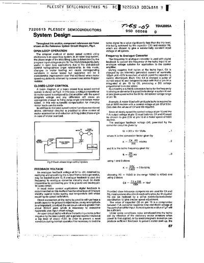
The document explains how the TDA2085A IC can be used for motor speed control, covering both open‑loop and closed‑loop operation, feedback voltage generation, and the role of the control amplifier.
It provides detailed circuit diagrams and design equations for the ramp generator, pulse‑timing circuit, triac gate drive, load‑current limiting, LED drive, AC and DC supply arrangements, and system interfacing such as CMOS logic and optical feedback.
| Transconductance gain | 100 µA/V |
|---|---|
| Output drive capability | ±25 µA |
| Zero voltage detector reset current | 50 µA |
| Ramp generator current source | 30 µA |
| C3 typical value (50 Hz supply) | 47 nF ±10% |
| Triac pulse width | ≈70 µs |
| LED drive additional current | ≈0.5 mA |
The zero voltage detector resets when the input current is between 50 µA.
The ramp generator uses an internally generated 30 µA current source (Ir).
The triac pulse width is approximately 70 µs.