
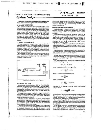
The TDA2085A is a motor‑speed‑control IC that can be used in both open‑loop and closed‑loop configurations. In open‑loop mode the triac firing angle is set by the program input voltage on pin 10, while closed‑loop operation compares an analogue feedback voltage on pin 13 with the speed reference on pin 10 to automatically adjust the firing angle.
The document provides extensive circuit diagrams, component value tables, and design equations for features such as the zero‑voltage detector, ramp generator, triac gate drive, LED drive, and overload protection. Application examples include universal motor drives for domestic appliances, optical feedback systems, and interfacing to CMOS logic for multi‑speed control.
| Transconductance gain | 100 µA/V |
|---|---|
| Output drive capability | ±25 µA |
| Zero‑voltage detector reset current | 50 µA |
| Typical C3 value (50 Hz) | 47 nF ±10 % |
| Typical C3 value (60 Hz) | 47 nF ±10 % |
| LED drive extra current | ≈0.5 mA |
| Dropper resistor power dissipation | < 2 W |
| Triac pulse width | ≈70 µs |
It resets when the input current falls between 50 µA.