
AD5933 is a high precision impedance converter system solution, which combines an on board frequency generator and 12-bit ADC, and can measure complex impedance.
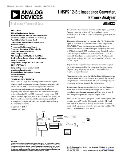
The AD5933 combines a frequency generator, a 12‑bit 1 MSPS ADC and an on‑board DSP to perform impedance measurements. It supports programmable sinusoidal excitation (2 V pk‑pk, 1 V, 500 mV, 200 mV) and provides real and imaginary data via an I²C serial bus.
The datasheet details specifications, timing characteristics, pin functions, register map, and operation of the DDS, ADC, and temperature sensor, enabling designers to integrate the part into biomedical, automotive, and other sensor applications.
| ADC Resolution | 12 bit |
|---|---|
| Impedance Range | 0.0001 Ω – 20 MΩ |
| Frequency Range | 0 – 50 kHz |
| Frequency Resolution | 27 bits (<0.1 Hz) |
| Output Voltage (pk‑pk) | 2 V |
| Power Supply | 3 V |
| Normal‑mode Current Consumption | 15 mA |
| I²C Clock Max Frequency | 400 kHz |
The I²C SCL clock can operate up to 400 kHz.
The temperature sensor measures from –40 °C to +150 °C.