
AD7861 is a 11-bit resolution, multichannel, simultaneous sampling A/D converter, designed for the acquisition of voltage inputs in a motor control solution or three-phase power system. The converter features an internal 2.5V reference, four simultaneously sampled input channels, and four multiplexed inputs.
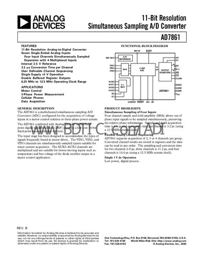
The AD7861 is an 11‑bit resolution, simultaneous‑sampling analog‑to‑digital converter designed for motor‑control and power‑measurement applications. It provides four input channels (VIN1‑VIN3 and one auxiliary) that can be sampled at the same time, a built‑in 2.5 V reference, and operates from a single +5 V supply.
The device features a 12‑bit parallel digital interface, register‑based I/O, and timing compatible with Analog Devices DSP families. Detailed pin descriptions, timing parameters, and mechanical dimensions are included for board‑level integration.
| Resolution | 11 Bits |
|---|---|
| Input Voltage Range | 0‑5 V |
| Reference Voltage | 2.5 V |
| System Clock Range | 6.25‑12.5 MHz |
| Conversion Time per Channel | 40 CLK cycles |
| Acquisition Time (Sample‑and‑Hold) | 1.6 µs (20 CLK cycles @ 12.5 MHz) |
| Supply Current (Ipp) | 10 mA max |
| Signal‑to‑Noise Ratio | ≥ 60 dB |
| Input Capacitance | 20 pF typ |
The AD7861 can sample up to four channels at the same time using its built‑in sample‑and‑hold amplifier.
It operates from a single +5 V supply and includes an internal 2.5 V reference.
The device works with an external clock between 6.25 MHz and 12.5 MHz.
Conversion results are stored in registers and read via a 12‑bit parallel interface; the LSB (Data Bit 0) is tied low.