
N310 Modbus communication protocol, introduces communication data structure, hardware installation, data frame, CMS, LRC LRC CHECK etc.
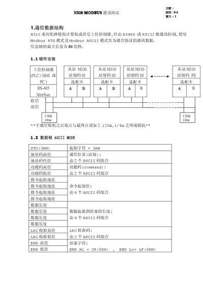
The N310 series uses RS‑485 or RS‑232 interfaces to communicate with a host controller via Modbus RTU or Modbus ASCII. The document defines the data frame structure, address mapping, function codes, and error handling for both modes.
It also lists the register map for control and monitoring, including command bits for start/stop, direction, frequency set‑points, and status bits for alarms and faults. CRC and LRC checksum calculations are provided for reliable data transmission. This manual is written in Chinese.
| Maximum data frame length | 80 bits |
|---|---|
| Maximum device address | 32 (0x20) |
| Minimum interval between command and response | 10 ms |
The data frame can be up to 80 bits long.
Addresses range from 00H (broadcast) up to 20H, allowing up to 32 devices.
A minimum interval of 10 ms must be maintained.