
This document mainly introduces the features and characteristics of the LEONARD rotary cam switch GSW100 series, including product structure, technical parameters, installation dimensions, etc.
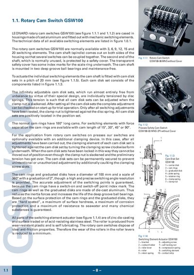
The Leonard GSW100 rotary cam switch is housed in a cast‑aluminum case with deep‑groove ball bearings and optional seawater‑proof protection. It is available with 3, 6, 9, 12, 15 or 20 switching elements, and the cam shaft features a 20 mm pitch for cam disk sets that are tensioned by disc springs.
The cam rings and graduated disks are 100 mm in diameter with a 360° scale and 2° graduation, providing precise switching angles. Detailed dimensions, weights and ordering information for each type (e.g., GSW100‑03, GSW100‑06) are listed in the tables.
| Available switching elements | 3, 6, 9, 12, 15, 20 |
|---|---|
| Cam shaft pitch | 20 mm |
| Cam ring diameter | 100 mm |
| Scale graduation | 360° total, 2° per division |
| Housing material | Aluminum alloy, painted RAL6011 |
| Dimensions (GSW100‑03) | A 105 mm, B 124 mm, C 114 mm, D 184 mm |
The GSW100 can be configured with 3, 6, 9, 12, 15, or 20 switching elements.
The cam disk sets are spaced with a 20 mm pitch on the cam shaft.
The housing is made of aluminum alloy and painted in RAL6011.
Cam rings have index marks for switch‑on and switch‑off points and are tensioned by disc springs; the clamp nut is tightened after adjustment.