
Describes how to use the HMI to connect to different brands, including communication speed, controller station number, control area/status area, controller wiring, controller Read/Write address definition, etc.
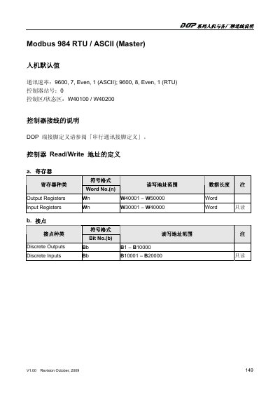
The document describes the default communication parameters for the Modbus 984 HMI, including baud rate, parity, and stop bits for both ASCII and RTU modes. It also lists the default controller station number and the address ranges for control and status areas.
Detailed tables define the register and I/O address formats, showing output and input register ranges as well as discrete output and input bit ranges. A note explains how to configure special Modbus write commands when required by the connected controller. This manual is written in Chinese.
| Communication speed (ASCII) | 9600, 7, Even, 1 |
|---|---|
| Communication speed (RTU) | 9600, 8, Even, 1 |
| Default controller station | 0 |
| Control/Status area addresses | W40100 / W40200 |
| Output register range | W40001 – W50000 |
| Input register range | W30001 – W40000 |
| Discrete outputs range | B1 – B10000 |
| Discrete inputs range | B10001 – B20000 |
The default ASCII communication speed is 9600 baud, 7 data bits, even parity, 1 stop bit.
The default controller station number is 0.
When a controller specifies a Modbus write command, a special parameter can be set; the default is Auto, which switches between single‑write (0x06) and multi‑write (0x10) based on data length.