
This file is about the connection instructions of the Siemens series HMI with various brands. It includes information such as communication speed, controller station number, control zone/status zone, DOP terminal definition, controller Read/Write address definition, etc.
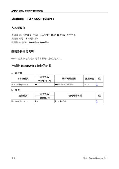
The document provides the default communication parameters for both ASCII and RTU modes, including baud rate, data bits, parity, and stop bits. It also lists the controller station number and the address ranges for control and status areas.
Detailed tables map Modbus addresses to the HMI internal registers for both volatile (Word) and non‑volatile (Bit) data, and the text includes wiring notes and register definitions for output registers and discrete outputs. This manual is written in Chinese.
| ASCII communication speed | 9600 baud, 7 data bits, Even parity, 1 stop bit |
|---|---|
| RTU communication speed | 9600 baud, 8 data bits, Even parity, 1 stop bit |
| Controller station number (default) | 1 |
| Control area / status area addresses | W40100 / W40200 |
| Output register address range | W40001 - W50000 |
| Discrete output address range | B1 - B2048 |
The default ASCII communication parameters are 9600 baud, 7 data bits, even parity, and 1 stop bit.
Modbus addresses map directly to internal registers; for example, Modbus address W40001 corresponds to internal register W40001, and address B00001 corresponds to internal bit register B0‑00001.
Discrete outputs are addressed from B1 to B2048.
The default controller station number is set to 1.