
The memory repair card is a memory stick test and repair tool that supports DDR266M, DDR333M, DDR400M memory frequencies and can accurately pinpoint the location of bad ICs on the memory stick.
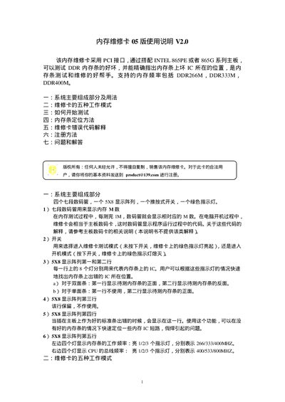
The manual describes the hardware components of the Memory Repair Card, including four seven‑segment displays, a 5×8 LED array, a push‑button switch and a green indicator light. It also lists the five operating modes such as fast/slow memory test, PC‑boot test and automatic shutdown after testing.
Instructions cover preparing a good reference memory module, connecting the card to an Intel 865PE/865G motherboard, running the test sequence, interpreting the LED and display codes, locating defective ICs, and registering the device for support. An error‑code section explains the meaning of codes like 00E0, 00E6 and 00EE, and a FAQ answers common usage questions. This manual is written in Chinese.
| Interface | PCI |
|---|---|
| Supported Memory Frequencies | DDR266M, DDR333M, DDR400M |
| Display Components | 4 seven‑segment displays, 5×8 LED array, push‑button switch, green indicator light |
| Memory Frequency Indicator LEDs | 1‑3 LEDs indicate 266/333/400 MHz |
| CPU Bus Frequency Indicator LEDs | 1‑3 LEDs indicate 400/533/800 MHz |
In principle it works on all Intel 865PE or 865G series boards, but some manufacturers add special functions that may affect compatibility.
The code 00E0 means the motherboard has no memory installed or the EP data of the installed module is unavailable or incorrect.
It indicates that the standard reference module and the test module have the same capacity, which prevents the test from proceeding.