
Mini PCI-E / LPC 笔记本诊断卡 II is an ideal tool for notebook computer repair. This diagnostic card supports Mini PCI-E, LPC bus interfaces and has code query functions. The diagnostic card can store sixteen codes and can be easily queried to any code through switches. This diagnostic card inherits the characteristics of easy to use and stable of the previous generation diagnostic card.
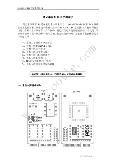
The Laptop Diagnosis Card II is a diagnostic tool that plugs into a notebook's Mini PCI‑E or LPC bus. It stores up to sixteen error codes and shows them on two seven‑segment displays with four indicator LEDs for clock, reset, bus and data signals. The manual describes the card's main components, connection methods, and how to use the code‑lookup switches.
Detailed sections cover the Mini PCI‑E pinout, the LPC pin definitions, wiring to various motherboard BIOS pins, and a table of IBM T6 diagnostic codes with explanations. Safety notes warn against connecting the 3.3 V pins to higher voltages. This manual is written in Chinese.
| Supported interfaces | Mini PCI‑E, LPC |
|---|---|
| Number of stored codes | 16 |
| Display type | Two 7‑segment LED displays |
| Signal indicator LEDs | Four (CLK, RST, LFRA, LAD) |
| Power supply | 3.3 V |
The card can store sixteen diagnostic codes that can be browsed with the lookup switches.
Pins 8, 10, 12, 14, 16, 17, 19 are used for the Mini PCI‑E interface.
Do not connect the card’s 3.3 V pins to a voltage higher than 3.3 V, as it can permanently damage the card.
They indicate the status of the clock (CLK), reset (RST), bus (LFRA), and data (LAD) signals.