
PT4107_DB03 is a full-voltage 20W LED daylight lamp switch constant current source, which is an AC non-isolated high-frequency switch-mode step-down constant current mode constant current source that can be installed in a 28mm lamp tube.
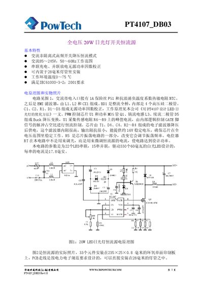
The PT4107_DB03 is a non‑isolated, high‑frequency switch‑mode constant‑current source designed for 20 W LED daylight lamps. It operates from an AC input of 85‑245 V at 50‑60 Hz and can be installed inside a 28 mm lamp tube. The circuit includes passive power‑factor correction, a buck converter, and a PWM controller to maintain a steady LED current.
The document provides the electrical parameters, a complete BOM, schematic diagrams, waveform measurements, and safety guidelines. It also explains how to adjust the output current with the precision potentiometer and how component choices affect performance and reliability. This manual is written in Chinese.
| Input voltage | 85–245 V |
|---|---|
| Power frequency | 50–60 Hz |
| Output voltage | 36–100 V |
| Output current | 200–256 mA |
| Switching frequency | 50 kHz |
| Efficiency | 90 % |
| Power factor | 0.9 |
| 3rd harmonic distortion | 17 % |
| 5th harmonic distortion | 15 % |
The device is designed for an AC input of 85 V to 245 V.
Because the board and LED pins are live, users must follow strict safety rules to avoid electric shock, and use appropriate high‑voltage probes when measuring.
It uses a passive, non‑isolated power‑factor correction circuit based on a half‑bridge topology with capacitors and diodes.