
This manual describes the installation, operation, and maintenance of the FMBA-01 Modbus adapter module.
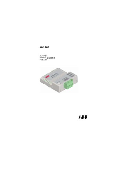
This manual provides safety guidelines, installation procedures, and wiring instructions for the ABB FMBA-01 Modbus adapter module. It is intended for qualified electrical engineers and technicians who work with ABB drive systems.
The document also contains technical specifications, LED diagnostic indicators, and fault‑diagnosis information to help users configure and maintain the module in RS‑485 networks. This manual is written in Chinese.
| Protection rating | IP20 |
|---|---|
| Power supply | +3.3 V ±5%, max current 150 mA |
| Connectors | 20‑pin (X2), 4‑pin (X1), 6‑pin jumper (J1) |
| LED indicators | 3 green LEDs (HOST, RXD, TXD) |
| Estimated life | 100 000 h |
| Compliance | UL/CSA, EN 50081‑2, EN 50082‑2 |
| Bus termination resistor | 120 Ω (built‑in) |
| Transmission medium | Shielded twisted‑pair, 100‑150 Ω |
| Maximum data rate | 5 Mb/s |
| Serial communication type | Asynchronous half‑duplex RS‑485 |
All electrical installation and maintenance must be performed by qualified electrical engineers, and the equipment must be properly grounded before any work.
The module has three green LEDs: HOST indicates the module is powered, RXD flashes when data is received from the bus, and TXD flashes when data is transmitted.
A 120 Ω termination resistor is built into the module and can be activated with jumper J1.
The module supports up to 5 Mb/s data rate on the RS‑485 link.