
This manual introduces the pin configuration, system structure, memory structure, addressing mode, stack, reset, clock and other contents of SONiX 8-bit microcontroller SN8P2501B.
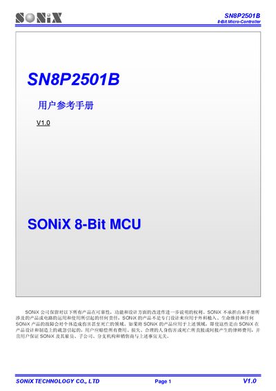
This reference manual describes the SN8P2501B 8‑bit microcontroller produced by SONiX. It covers the device’s pin layout, memory organization, register set, interrupt system, timer functions, PWM output, and I/O port behavior, as well as package options and electrical characteristics.
Key sections include pin assignment tables, detailed descriptions of each pin’s function, memory sizes (OTP ROM and RAM), system registers, various operating modes (normal, low‑speed, sleep, wake‑up), interrupt sources, timer/counter configurations, and PWM duty‑cycle control. The document also lists the available package types (PDIP‑14, SOP‑14, SSOP‑16) and provides clock source options such as internal RC oscillators and external crystal connections. This manual is written in Chinese.
| OTP ROM size | 1K × 16 bits |
|---|---|
| RAM size | 48 × 8 bits |
| Package options | PDIP 14 pins, SOP 14 pins, SSOP 16 pins |
| Low‑speed RC oscillator | 16 kHz @3 V, 32 kHz @5 V |
| High‑speed RC oscillator | up to 10 MHz |
| LVD level | 3‑Level LVD |
The OTP ROM is 1 K × 16 bits.
It is available in PDIP‑14, SOP‑14, and SSOP‑16 pin packages.
The device supports an internal low‑speed RC (16 kHz @3 V, 32 kHz @5 V), an internal high‑speed RC up to 10 MHz, and an external crystal up to 16 MHz.