
The document provides quick steps for testing the minimum essentials of a motherboard before installation. It includes visual aids and emphasizes the importance of safety precautions. The EVGA nForce 790i SLI TM FTW motherboard is specifically mentioned. The steps include removing the protective cover, installing an Intel processor, applying thermal paste, installing a heatsink and fan, inserting system memory, connecting a keyboard, and connecting the power supply. The document highlights the need for ESD countermeasures and safe handling practices.
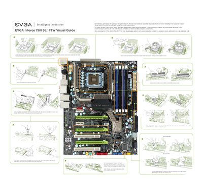
This quick install guide walks you through the essential steps to test and install the EVGA nForce 790i SLI FTW motherboard before placing it in a chassis. It includes safety reminders, ESD precautions, and visual aids to help avoid damage during handling.
The guide details CPU installation, memory module placement, graphics card insertion, and connection of power and peripheral cables. It also notes the motherboard’s key features such as three PCI‑Express X16 slots, four DDR3 memory slots, and the required 24‑pin ATX and 8‑pin CPU power connectors.
| CPU socket type | LGA 775 |
|---|---|
| Memory slots | Four 240‑pin DDR3 DIMM slots |
| PCI Express slots | Three PCI‑Express X16 slots |
| Power connectors | 24‑pin ATX and 8‑pin CPU power connectors |
Unlock the socket lever, lift the load plate, remove the protective cover, align the CPU notches with the socket, lower the CPU, close the load plate and re‑engage the lever.
The board supports up to four 240‑pin DDR3 memory modules, with dual‑channel operation recommended using matched pairs.
Use the PCI‑E slot that is closest to the CPU socket when installing a single graphics card.
Connect the 24‑pin ATX power connector and the 8‑pin CPU power connector to the board before powering on.