
PLA Multi PL Control Unit allows multiple PL series charge controllers to work simultaneously and provides a common communication interface. It also provides four alarm or control channel outputs, as well as control of a LS1 load switch and load current measurement unit. PLA can connect up to 3 PL controllers.
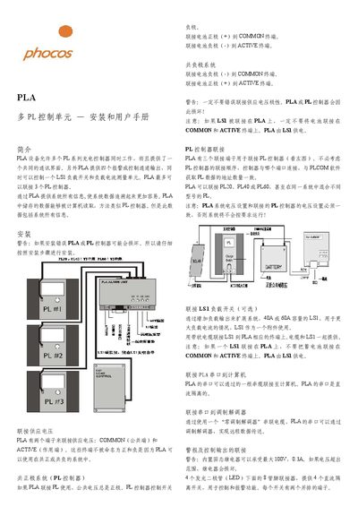
The Phocos PLA control unit allows multiple PL series charge controllers to work together through a common communication interface. It provides four alarm/control outputs, a load switch (LS1) and load‑current measurement. The unit can connect up to three PL controllers and stores system data that can be read by a computer.
The guide covers power‑supply wiring for both common‑positive and common‑negative systems, PL controller connections, LS1 load‑switch integration, serial communication setup, alarm and LED indicators, and detailed configuration of voltage limits, baud rates and synchronization of charging modes across all connected controllers. This manual is written in Chinese.
| Maximum Alarm Relay Rating | 100 V, 0.3 A |
|---|---|
| Baud Rate Options | 300, 1200, 2400, 9600 |
| Maximum Load Current Measurement | 255 A |
| Maximum Battery Capacity Measurement | 4000 Ah |
| Operating Temperature Range | -20 °C to 60 °C |
| Maximum Output Voltage/Current | 100 V, 0.3 A |
For a common‑positive system connect the battery positive (+) to the COMMON terminal and the negative (‑) to the ACTIVE terminal; for a common‑negative system connect the negative (‑) to COMMON and the positive (+) to ACTIVE.
The PLA’s RS‑232 serial port is connected to the computer with a serial cable, and communication is performed using the PLCOM software at the selected baud rate.