
The AMDP-X/F1 series motor protectors are equipped with 4-20mA analog output, which can be set to the current range of phases A, B, and C according to parameter C, as well as the zero-sequence current range proportional to the voltage. These four analog outputs are isolated from the acquisition, protection circuit, and DSP.
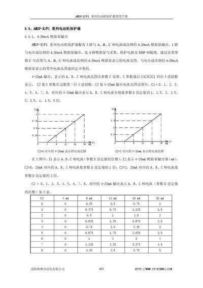
The AMDP‑X/F1 series motor protector provides four 4‑20 mA analog outputs – three proportional to the A, B, C phase currents and one proportional to voltage – with configurable current ranges and voltage display options. The manual details how to set parameters such as working current, start‑up and stall protection times, overload and imbalance protection, as well as self‑reset functions.
Wiring diagrams show connections for the main unit, current transformers and zero‑sequence transformer, and specify that the IA/IB/IC and zero‑sequence wires must remain connected during operation. Additional series (F10, F11, F12‑F17) share similar features with variations in protection functions and parameter options. This manual is written in Chinese.
| Analog output channels | 4 (3 current proportional, 1 voltage proportional) |
|---|---|
| Maximum output load resistance | < 600 Ω |
| Current transformer primary rating | Selectable 100,150,200,300,400,500,600,800 A |
It has four channels – three proportional to the A, B, C phase currents and one proportional to voltage.
The short‑circuit protection time is set to 0.3 seconds.