
This document is about the operation and maintenance manual of the R200 regulator. It provides information on the precautions and procedures for using the regulator with an upstream fully open monitor. The document covers the pre-work status of the system, system depressurization, pre-testing considerations, debugging sequence, and inspection operations.
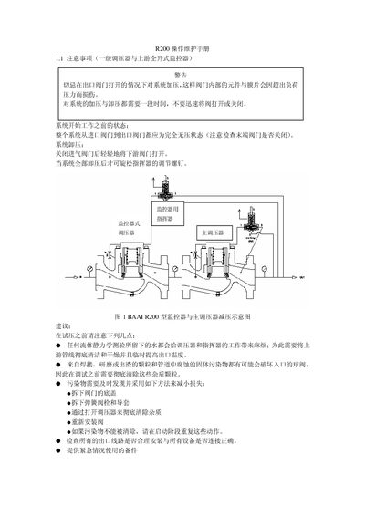
This manual provides detailed instructions for preparing the R200 pressure regulator system, including safety warnings, system pressurization, and depressurization steps. It explains the required checks before operation, such as ensuring all valves are closed and the system is fully depressurized.
The document also outlines the adjustment sequence for the monitor and actuator, pressure set‑point selection guidelines, and troubleshooting tips for leaks and contamination. Recommended limit‑setting ranges and pressure set‑point formulas are included to achieve stable control. This manual is written in Chinese.
| Recommended limit‑setting range | 1.0 – 2.0 |
|---|---|
| Typical control screw position for monitor limit | ≈ 4.0 |
| Pressure set‑point formula (monitor) | Monitor set‑point = Actuator set‑point + 100 kPa (HP range) |
| Pressure set‑point formula (monitor, low range) | Monitor set‑point = Actuator set‑point – 150 kPa (MP range) |
The limit‑setting should be set between 1.0 and 2.0 for most applications.
Close the inlet valve, then gently open the downstream valve until the system is fully depressurized before turning the monitor adjustment screw.
For the high‑pressure range, monitor set‑point = actuator set‑point + 100 kPa; for the medium‑pressure range, monitor set‑point = actuator set‑point – 150 kPa.
Set the limit‑setting screw to approximately the 4.0 position on the control scale.