
BM1410A application guide, introducing the application circuit of the product, including input capacitance, output inductance, diode, resistance and other components selection and precautions
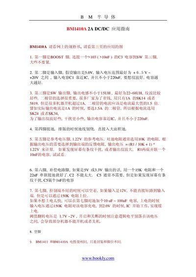
The document provides a detailed guide for designing circuits with the BM1410A DC/DC converter. It describes each pin’s purpose, recommended external components, and practical PCB layout tips to achieve low ripple and stable operation.
Key recommendations include placing input and output capacitors close to the IC, using inductors of 22‑68 µH, selecting diodes rated at 1.5 × the maximum output current, and following the special notes for low‑voltage applications and alternative part substitutions. This manual is written in Chinese.
| Input Voltage Range | +6.5 V to +20 V |
|---|---|
| Reference Voltage | 1.22 V |
| Output Capacitor Minimum | ≥ 220 µF |
| Output Inductance | ≥ 1 µH, recommended 22‑68 µH |
| Diode Current Rating | 1.5 × maximum output current |
The input voltage should be between +6.5 V and +20 V.
It uses a 1.22 V reference voltage.
The diode should be rated at least 1.5 times the maximum output current.