
This document is an instruction sheet for CME-DN01. It introduces the panel appearance, dimensions, wiring and settings, mounting method and power supply of CME-DN01.
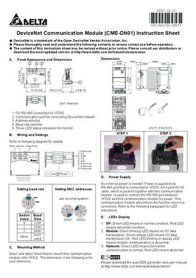
This manual describes the CME-DN01 DeviceNet communication module, including its physical layout, connection methods, and operating indicators. It is intended for installers and users who need to integrate the module with a VFD‑E inverter.
Key sections cover panel appearance and dimensions, wiring and baud‑rate settings, mounting steps, power supply via the RS‑485 port, and interpretation of the three LED status indicators. This manual is written in Chinese.
| Panel width | 72.2 mm (2.84 in) |
|---|---|
| Panel height | 57.3 mm (2.26 in) |
| Panel depth | 14.3 mm (0.57 in) |
| Baud rate options | 125K, 250K, 500K |
| Power supply | Supplied via RS‑485 port, no external power needed |
The module does not require an external power source; power is supplied through the RS‑485 connection to the VFD‑E.
SP green means normal, red means abnormal; Module green blinking indicates no I/O data, green steady means I/O data OK, red indicates abnormal; Network green shows normal DeviceNet communication, red shows abnormal.
Use the BAUD0 switch: position 0 selects 125 Kbps, 1 selects 250 Kbps, and 2 selects 500 Kbps.