
The XLSEMI XL6019 Demo Board Manual provides schematic, pin description, BOM, performance data, and PCB layout for the XL6019 DC‑DC converter demo board.
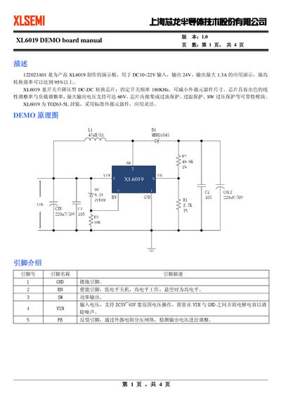
This manual describes the XL6019 demo board, which demonstrates the XL6019 switching step‑up/step‑down DC‑DC converter chip. It outlines the board’s input range of 5 V‑40 V, a fixed 180 kHz switching frequency, and an output of 24 V up to 1.3 A with up to 95% efficiency.
The document includes a schematic, detailed pin descriptions, a complete bill of materials, performance graphs, a physical photo of the demo board, PCB layout diagrams, and layout guidelines to help users assemble and test the board safely.
| Input voltage range | 5 V‑40 V |
|---|---|
| Maximum output current | 1.3 A |
| Switching frequency | 180 kHz |
| Maximum conversion efficiency | ≥95 % |
| Package type | TO263-5L |
| Integrated protection | Over‑current, over‑temperature, SW over‑voltage |
The board supports an input voltage range of 5 V to 40 V.
It delivers a 24 V output with a maximum current of 1.3 A.
The chip uses a fixed switching frequency of 180 kHz.
It includes over‑current, over‑temperature, and SW over‑voltage protection.