
This manual provides safety instructions, technical specifications, installation, operation, and maintenance details for the XJCKYB Power Energy Combination…
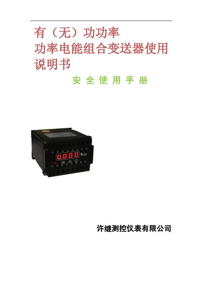
The manual begins with safety warnings and general overview of the Power Energy Combination Transmitter, describing its function of converting measured power and energy parameters into isolated analog or digital signals with RS‑485 communication. It also lists the applicable standards and guarantees.
Subsequent sections cover technical specifications, installation requirements, wiring diagrams, operation procedures, programming details, digital interface configuration, ordering information, and maintenance guidelines. The document is intended for qualified personnel only. This manual is written in Chinese.
| Rated measurement range (current) | 0‑5 A or CT secondary |
|---|---|
| Rated measurement range (voltage) | 0‑100 V (380 V) or PT secondary |
| Frequency range | 45‑55 Hz |
| Accuracy class | XP 0.5, JP 0.2 |
| Operating temperature | -10 °C ~ 55 °C |
| Response time | < 300 ms |
| Output signal | 4‑20 mA or 1‑5 V, isolated |
| Communication interface | RS‑485, Modbus‑RTU |
| Load resistance (current output) | < 550 Ω |
| Load resistance (voltage output) | > 5 kΩ |
| Auxiliary power | AC/DC 220 V 50 Hz ± 2.5 Hz |
| Physical dimensions | 110 × 75 × 120 mm |
| Installation method | 35 mm DIN rail or Φ5 mm / Φ4 mm screw |
The default password is 1111.
It uses the Modbus‑RTU protocol.
The device can be mounted on a 35 mm DIN rail or secured with Φ5 mm or Φ4 mm screws.