
Design guide for the TYHX HRS3300 optical heart rate sensor, covering installation, application, schematic, and PCB design considerations.
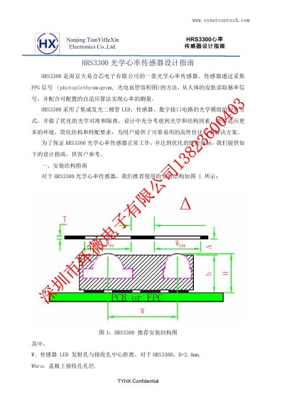
This document provides detailed design guidelines for integrating the TYHX HRS3300 optical heart rate sensor. It covers installation structure, application recommendations, schematic design, and PCB layout considerations. The sensor uses integrated LED, sensor, and digital interface circuitry for optimized optical alignment and isolation. It is designed for wearable applications such as smartwatches and fitness trackers, with specific guidance on cover plate thickness, air gap, and isolation band dimensions to ensure accurate PPG signal acquisition.
The guide also addresses power considerations, including LED driving methods and voltage requirements, and discusses signal characteristics such as baseline variations and motion interference. It includes practical tips for optimizing performance in different environments and with different skin types or placement locations (e.g., wrist vs. fingertip). This manual is written in Chinese.
| Air Gap Distance | <0.3mm |
|---|---|
| Cover Plate Thickness | 0.8mm |
| Isolation Band Width | 0.8mm |
| Operating Voltage for VLEDA | 3.3V or higher |
The recommended air gap distance should be less than 0.3mm. If structural constraints prevent this, it can be relaxed to within 1mm, with algorithm adjustments to maintain data quality.
The cover plate should be made of transparent materials such as glass, acrylic, or resin, or materials that allow 525nm green light to pass through.
VLEDA should be at least 3.3V, as lower voltages may cause LED brightness fluctuations and introduce noise.
Yes, the INT pin can be left floating, and the corresponding I2C pull-up resistor can be omitted.