
Installation instructions for Solinst's Levelogger Model 615 in a Drive-Point piezometer, including required components and step-by-step procedure using a…
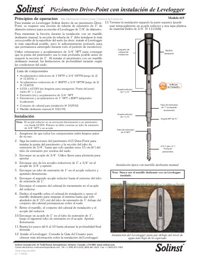
This guide details how to install the Solinst Levelogger Model 615 into a Drive-Point piezometer. It lists required components like reducers, extension tubes, and a manual slide hammer. The procedure involves assembling the system with 3/4" and 1" NPT fittings, pushing it into the ground using the slide hammer, and finishing with a cap. Special notes address compatibility and operational safety. This manual is written in Spanish.
Install the Levelogger as shallow as possible while ensuring it remains submerged during monitoring.
A 1-inch diameter internal extension pipe section is required to accommodate the Levelogger.
Only about 6 inches (15 cm) of the extension pipe should remain above the ground.
About 6 inches (15 cm) of the 1-inch extension pipe below the installation head assembly should remain above the ground.