
Chinese user manual for the QSD‑Z series Q‑switch driver covering specifications, installation, operation and troubleshooting.
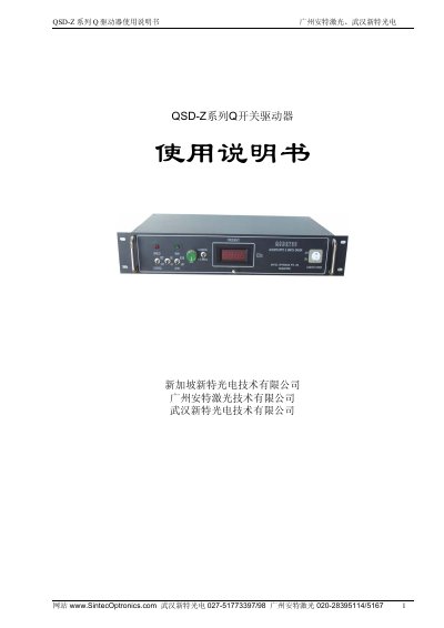
The manual introduces the QSD‑Z series Q‑switch driver, a high‑precision acoustic‑optic Q‑switch power supply designed for various Q‑switch devices. It describes the driver’s compact structure, key technical parameters and unique features such as first‑pulse suppression and dual‑range modulation.
Detailed sections cover the operating principle, RF unit, control board, impedance matching, wiring, panel functions, installation requirements, and a troubleshooting guide with common fault symptoms and remedies. This manual is written in Chinese.
| Operating frequency | 27.125 MHz |
|---|---|
| RF output power | ≥50 W (at 45 °C) |
| Input voltage | AC 220 V |
| Input power | <180 W |
| Voltage standing wave ratio | ≤1.2 (50 Ω load) |
| Chassis size | 19‑inch 2U (483 × 88 × 270 mm, 5.5 kg) |
The standing‑wave ratio should be less than 1.2.
The driver provides 0.5 kHz – 5 kHz and 5 kHz – 50 kHz modulation ranges.