
The Ruite 5R42 user manual provides specifications, wiring, configuration, and safety information for the five‑phase stepper motor driver.
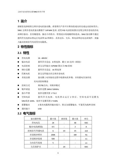
The 5R42 is a five‑phase stepper motor driver that uses SVPWM technology and PID current control to achieve high‑precision, low‑vibration motion. It supports 8 current settings and 16 micro‑step divisions, with over‑voltage, under‑voltage, phase‑current and total‑current protection, and all control signals are optically isolated.
The manual covers electrical specifications, port and wiring diagrams, power‑supply requirements, motor connection, control‑signal wiring, timing diagrams, parameter settings, LED status indicators, installation instructions, warranty terms, and contact information for service and sales. This manual is written in Chinese.
| Supply Voltage | 24‑48 VDC |
|---|---|
| Peak Output Current | 0.5‑2 A |
| Control Signal Conduction Current | 6‑15 mA |
| Step Pulse Frequency | 200 k‑1 MHz |
| Step Pulse Width | 500 ns |
| Direction Signal Width | 5 µs |
| Undervoltage Protection Point | -20 VDC |
| Overvoltage Protection Point | -55 VDC |
| Input Signal Voltage Range | 3.3‑7 VDC |
| Driver Initialization Time | 2 s |
The driver operates with a supply voltage of 24 V to 48 V DC.
Eight current settings can be selected via the DIP switches.
A steady green LED means the driver is not enabled.