
The Qingsheng QS-FS wind speed sensor manual provides specifications, installation, MODBUS communication, troubleshooting, and maintenance guidelines.
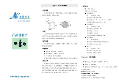
The QS-FS wind speed sensor is a compact, lightweight device designed for easy transport and installation. It features a three‑cup design for accurate environmental data collection and is built from high‑quality polymer carbon fiber for corrosion resistance and long‑term durability.
The manual covers physical dimensions, material details, applicable environments, key features, mounting methods, technical parameters for voltage, current, pulse, and 485 output types, MODBUS protocol settings, wiring color codes, usage precautions, common fault troubleshooting, and recommended maintenance practices. This manual is written in Chinese.
| Startup Wind Speed | 0.2‑0.4 m/s |
|---|---|
| Voltage Output – Measurement Range | 0 ~ 32.4 m/s |
| Voltage Output – Supply Voltage | 7 V ~ 24 V DC |
| Voltage Output – Signal | 0.4‑2 V or 0‑5 V, 1‑5 V |
| Current Output – Measurement Range | 0 ~ 32.4 m/s |
| Current Output – Supply Voltage | 12 V ~ 24 V DC |
| Current Output – Signal | 4 ~ 20 mA |
| Pulse Output – Measurement Range | 0 ~ 60 m/s |
| Pulse Output – Signal | Pulse (1 pulse = 0.88 m/s) |
| 485 Type – Communication Speed | 9600,n,8,1 |
The station address can be modified by sending a specific command sequence; for example, Method 1 uses the command "02 10 10 00 00 01 02 00 03 CRC" after adjusting the address byte.
For the voltage output type, the power line uses red or brown, ground uses blue, and the signal line uses yellow.
The current output model should be powered with 12 V to 24 V DC.