
The Preston Cinema Systems Digital Micro Force Service Manual explains power connections, operation, adjustments, and troubleshooting for the zoom‑lens…
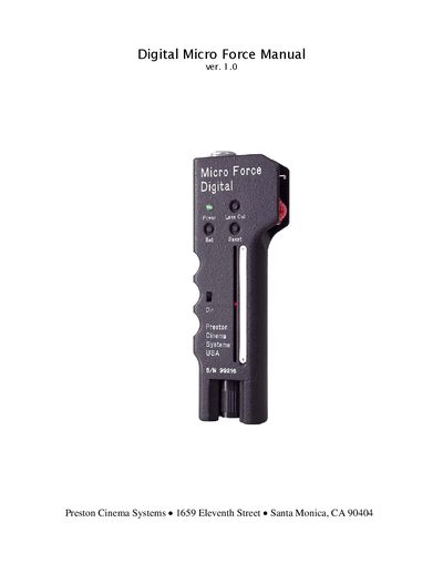
This manual describes the Digital Micro Force controller, a solid‑aluminum device that drives DM1 or DM2 digital motors for film and video lenses. It details power options, wiring, and the unique digital features such as automatic lens calibration, electronic limit setting, and a LED bar‑graph display.
The guide also provides step‑by‑step adjustment procedures, a full pin‑out reference, and a troubleshooting section to help technicians diagnose power, motor, and joystick issues, as well as a complete accessory list.
| Voltage range | 11 – 30 VDC |
|---|---|
| Idle current (24 VDC) | 55 mA |
| Power supply outputs | +5 V, +9 V, +24 V |
| Typical current consumption (12 V input) | 95 mA |
| Analog‑mode current consumption | 13 mA |
It operates over a voltage range of 11 – 30 VDC.
Press the Set button, move the lens to the first limit with the joystick, then press the Set button again and move to the second limit; the lens will stop at those positions.
Verify the power source, battery, and accessory socket; try an auxiliary power cable and ensure the thermal fuse is not tripped.
Measure the voltage between test points 3 and 4 with no joystick pressure and adjust VR2 until the reading is less than 0.10 mV.