
Repair manual for the MSTAR 8M20 series chipset covering power distribution, signal I/O, flash memory, DDR, RF tuner and troubleshooting.
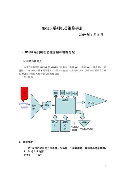
The manual provides a detailed overview of the 8M20 series chipset functions, power distribution, and control signal interfaces. It describes the internal power rails, voltage conversion circuits, and the pin assignments for HDMI, PWM, IR, and other control signals.
It also includes sections on the serial flash memory, DDR SDRAM specifications, RF tuner module, factory mode operations, software debugging guidance, and step‑by‑step troubleshooting procedures for common faults such as no signal, screen artifacts, and sensor failures. This manual is written in Chinese.
| Standby voltage (5VST) | 5 V |
|---|---|
| Standby current | ≈520 mA |
| Flash memory size | 4 Mbit serial flash |
| DDR SDRAM size | 128 Mbit |
| DDR SDRAM clock rate | 250 MHz |
| DDR SDRAM supply voltage | 2.5 V |
| RF tuner model | HFT-8B/115CW |
Press the volume‑minus button and, while holding it, press the remote’s screen‑display key.
The DDR SDRAM is supplied with 2.5 V.
The MP1482 power‑conversion chip handles the DC‑DC conversion and current monitoring.