
The Micro-Imagechecker A210/A110 Series user manual provides safety guidelines, installation steps, and operation instructions for the controller and its…
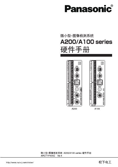
This manual covers safety precautions, hardware description, and wiring details for the Micro-Imagechecker A210/A110 series. It explains the functions of the controller, camera modules, connectors, and LEDs, and lists required power and environmental limits.
The document also includes specifications for power supply, input/output ports, flash synchronization, and revision history, helping technicians install, configure, and maintain the system safely and correctly.
| Controller weight | ≈ 300 g |
|---|---|
| Controller dimensions | 40 × 120 × 50 mm |
| Camera weight | ≈ 70 g |
| Camera dimensions | 29 × 31 × 54.5 mm |
| Controller power supply | DC 24 V |
| External supply voltage range | 12 V–24 V DC |
| Maximum output load current | 24 mA per signal |
| Flash output timing (NPN) | ≤ 550 µs |
| Flash output timing (Photo‑Mos) | ≤ 450 µs |
Users must read the manual, avoid combustible gases, never open the unit, ensure proper grounding, and follow all warning and caution notices to prevent injury or damage.
The controller must be supplied with a DC 24 V power source.
The A210 controller provides two camera connectors (Camera A and Camera B).
Each output channel can drive up to 24 mA.