
The DMA1182c two‑phase stepper driver manual from Lisan Electromechanical provides specifications, wiring diagrams, setup, and troubleshooting for the device.
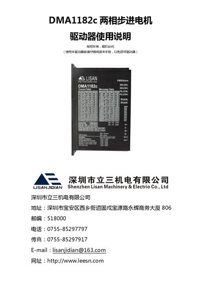
The DMA1182c is a digital two‑phase stepper driver from Lisan Electromechanical, featuring PI control, low noise, low vibration, low heat and a peak output current up to 8.2 A. It supports 16 current settings and 16 micro‑stepping options, with built‑in over‑/under‑voltage protection and phase‑open detection.
The manual includes a product overview, electrical and environmental specifications, mechanical installation and heat‑dissipation guidance, detailed port descriptions and wiring instructions, current/micro‑stepping configuration tables, power‑supply selection, motor connection advice, protection function explanations, a troubleshooting FAQ and warranty information. This manual is written in Chinese.
| Output current (peak) | 2.2 – 8.2 A |
|---|---|
| Control signal current | 5 – 20 mA |
| Step pulse frequency | 0 – 300 kHz |
| Under‑voltage protection point | 17.5 VDC |
| Over‑voltage protection point | 200 VDC |
| Insulation resistance | 500 MΩ |
| Storage temperature | -20 °C – 65 °C |
| Weight | 350 g |
The LED pattern signals a fault: green‑red 1‑1 means phase over‑current, 1‑2 means motor phase open, 1‑3 means high supply voltage, 1‑4 means low supply voltage, and 1‑5 indicates other faults.
The output current is selected with the DIP switches; for example, setting the switches to ON‑ON‑ON‑ON gives a peak current of 8.2 A.
The driver accepts step pulses up to 300 kHz.
The driver provides over‑voltage, under‑voltage, phase‑over‑current, and motor‑phase open detection, each indicated by specific LED patterns.