
This manual explains installation, wiring, operation, and troubleshooting of the Jinyun Pioneer XWK2/JKLX smart reactive power automatic compensation…
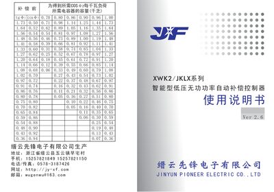
The XWK2/JKLX series is a low‑voltage reactive power compensation controller designed for distribution systems. It can be used with various low‑voltage static capacitor banks and offers features such as memory after power loss, LED power‑factor display, and strong anti‑interference capability.
The manual covers product introduction, key features, installation methods, wiring diagrams, panel functions, parameter setting, automatic and manual operation modes, fault diagnosis, and warranty information, providing step‑by‑step guidance for users and technicians. This manual is written in Chinese.
| Power factor (Cosφ) range | 0.70 to -0.70, typical 0.97 |
|---|---|
| Over‑voltage protection value | 430 V |
| Switching delay per channel | 30 s |
| Maximum operating altitude | ≤1000 m |
| Operating temperature range | -40 °C to +40 °C |
| Maximum relative humidity | ≤85 % (at 25 °C) |
Press the setting key to light the Cosφ indicator, then use the increase/decrease keys until the digital display shows the desired Cosφ value.
The over‑voltage indicator lights, the digital Cosφ display switches to show the current grid voltage, and the controller gradually disconnects capacitor groups every 2 seconds.
Use the manual/automatic switch; in automatic mode the controller tracks the grid power factor and controls capacitor banks, while in manual mode you can insert or remove capacitors with the panel keys.
The sampling current must be greater than 150 mA; otherwise the digital Cosφ display shows 0.cc.