
This manual covers communication connections, parameter settings, and application examples for the Hollysys HS/LS Series digital AC servo drives using…
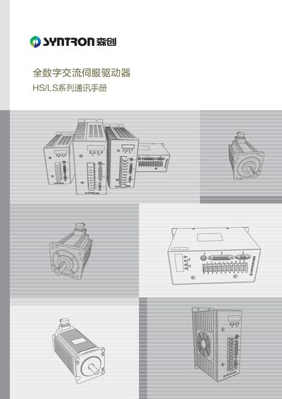
This manual provides detailed instructions for the Hollysys HS/LS Series full-digital AC servo drives. It covers communication terminal wiring, including RS232, RS485, and CAN bus connections, as well as the necessary 120Ω matching resistor setup for networked applications.
The document details how to configure bus application and control modes via specific parameters. It explains the MODBUS and CAN bus communication protocols, including register address allocations for status, parameters, and commands, and provides specific message formats for read/write operations in question-answer, point-to-point, broadcast, and report modes. This manual is written in Chinese.
| Core Control Unit | TI DSP chip with dual-core processing capability |
|---|---|
| Controlled Motor Type | Permanent magnet synchronous servo motors |
| Supported Communication Buses | MODBUS and CAN bus |
| Fault History Records | 8 levels |
The HS series supports MODBUS communication via RS232 or RS485, and CAN bus communication.
The driver does not provide a system-level 120Ω matching resistor; users must connect it themselves when networking.
Error code 1301 indicates a communication timeout alarm (Time Out).