
This application guide provides circuit diagrams, PCB layout tips, testing procedures, and EMC improvement measures for the HM1480 2A car charger.
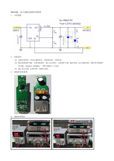
The HM1480 2A is a car‑mounted charger featuring a simple application circuit with few external components, low system cost and high reliability. It includes output short‑circuit protection, built‑in over‑temperature protection, input over‑voltage protection and adjustable over‑current protection. The device operates from an input voltage range of 8‑30 V DC and is supplied in an SOP‑8 package.
The guide details PCB layout recommendations such as keeping power traces wide and short, routing the FB pin away from the SW signal, and placing input capacitors close to the VIN and GND pins. It also covers demo board PCB layout, testing procedures, precautionary measures, and EMC improvement steps like minimizing loop area and adding a 10 Ω + 1 nF snubber to suppress switching spikes. This manual is written in Chinese.
| Input voltage range | 8‑30 V DC |
|---|---|
| Package | SOP‑8 |
| Protection features | output short‑circuit, over‑temperature, input over‑voltage, adjustable over‑current |
| Output current formula | Ics = 100 mV / R1 |
The charger operates with an input voltage between 8 V and 30 V DC.
It includes output short‑circuit protection, built‑in over‑temperature protection, input over‑voltage protection, and adjustable over‑current protection.