
The manual provides specifications, interface definitions, electrical characteristics, timing diagrams and usage instructions for the HTW‑G320240B1 LCD module.
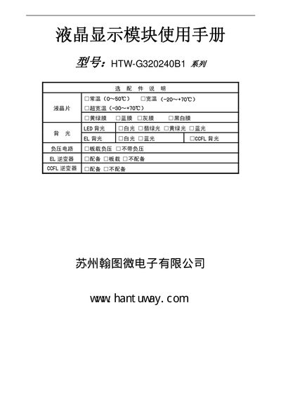
This document describes the HTW‑G320240B1 liquid‑crystal display module, including its mechanical dimensions, electrical parameters, and functional features such as 320×240 STN LCD, 64 KB display RAM and built‑in character generator. It also explains how to select the appropriate controller timing (Intel8080 or M6800) via hardware settings.
Detailed sections cover hardware wiring, backlight options, reset circuitry, timing diagrams for both supported interfaces, software command set, and extensive handling precautions (static protection, soldering limits, storage conditions). The appendix lists backlight voltage/current options and safety notes for reliable operation. This manual is written in Chinese.
| Supply voltage | 5.0 V ± 10 % |
|---|---|
| Resolution | 320 × 240 dots |
| LCD type | STN, 1/240 duty, 1/17 bias |
| Display RAM | 64 KB |
| Number of built‑in fonts | 160 × 5×7 dot fonts |
| Maximum module current (excluding backlight) | <120 mA |
| LCD drive voltage (Vop) | 30 V max |
| Input high level (VIH) | 0.5 Vdd ~ Vdd |
| Input low level (VIL) | 0 V ~ 0.2 Vdd |
| Output high level (VOH) | ≥2.4 V |
| Output low level (VOL) | ≤0.4 V |
It operates from a 5.0 V supply with a tolerance of ±10 %.
The LCD provides a 320 × 240 dot matrix display.
The reset line (/RES) is a Schmitt‑trigger input; a low level longer than 200 µs triggers a reset.