
The GT KLM N03 Light Control Module User Manual provides an overview, wiring diagram, indicator functions, and dip‑switch address settings.
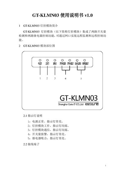
The GT‑KLM N03 light control module integrates two switch‑input detections and two relay‑output controls, and can be monitored and controlled remotely via an Ethernet port. It is designed for 12 V DC power supply and supports 10/100 M adaptive Ethernet networking.
The manual describes the indicator light meanings, terminal connections for power, switch inputs, relay outputs, and Ethernet, as well as the dip‑switch settings used to configure the module's address in binary form. This manual is written in Chinese.
| Power supply | 12 V DC |
|---|---|
| Network interface | 10/100 M adaptive Ethernet |
| Switch inputs | 2 (each with 2 kΩ pull‑down when unused) |
| Relay outputs | 2 (NO/NC/COM contacts) |
| Functional capability | Two switch‑input detections and two relay controls |
The lights show power status, module operation, communication activity, switch‑input alarm, and relay activation as described in the manual.
The address is set with the dip‑switch using binary values from 1 to 255; the lowest bit is position 1 and the highest is position 8.