
The GBEM235 analog combination expansion module manual provides specifications, wiring diagrams, calibration steps, configuration switches, and address…
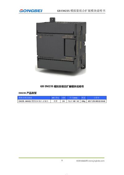
The GBEM235 is a 4‑channel analog input, 1‑channel analog output expansion module. It accepts voltage signals from ±25 mV up to ±10 V and current signals from 0‑20 mA, with selectable ranges via DIP configuration switches. The module operates on a 24 VDC supply and draws about 2 W.
The manual covers product selection, physical dimensions, power indicators, wiring diagrams, calibration procedures, DIP switch settings, address allocation through S7 PLC software, and common troubleshooting tips such as power‑up sequencing and address errors. This manual is written in Chinese.
| Analog Input Channels | 4 |
|---|---|
| Analog Output Channels | 1 |
| Input Current Range | 0‑20 mA |
| Output Voltage Range | ±10 V |
| Output Current Range | 0‑20 mA |
| Maximum Input Voltage | 30 VDC |
| Maximum Input Current | 32 mA |
| Resolution | 12 bits (11 data + 1 sign) |
| Accuracy | ±0.5 % of full scale |
| Establishment Time | 100 µs (voltage), 2 ms (current) |
When the LED is lit, the 24 VDC power is normal and the module is correctly connected to the controller; when it is off, the power is abnormal or the connection to the controller has failed.