
The FARE FP5139 application note describes the IC’s architecture, pin functions, design limits, soft‑start, short‑circuit protection, and provides example…
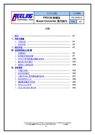
This application note explains the FP5139 boost‑converter controller IC. It covers the internal block diagram, pin descriptions, functional theory, and design equations for a high‑efficiency step‑up power supply.
The document includes design‑limit guidelines, soft‑start and short‑circuit protection operation, PWM comparator behavior, PCB layout tips, and a complete bill of materials for an evaluation board. This manual is written in Chinese.
| Reference voltage | 0.5 V ± 2 % |
|---|---|
| Operating voltage range | 1.8 V ~ 13.5 V |
| Operating frequency range | 50 kHz ~ 1 MHz |
| UVLO threshold | ≈ 1.3 V |
| Maximum PWM duty cycle | 85 % |
| Shutdown mode | Enabled |
| Package types | SOP‑8L / TSSOP‑8L / MSOP‑8L |
The FP5139 provides a 0.5 V reference voltage with a tolerance of ±2 %.
During power‑on, the soft‑start circuit limits the PWM duty cycle until the output voltage reaches a stable level, preventing a sudden jump to full duty.
If a short‑circuit is detected after soft‑start, the FP5139 disables the PWM output and enters a lock‑up state until power is cycled or the BR/CTL pin releases it.
The IC limits the PWM duty cycle to a maximum of 85 %.