
Installation and operation manual for the F4 microcomputer controller, covering features, specifications, wiring, and usage instructions.
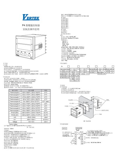
The manual introduces the F4 microcomputer controller, highlighting its compact design, flexible input options (thermocouples, PT100, voltage, current), and configurable control outputs such as relay, SSR, current and voltage. It also details communication via RS‑485 Modbus RTU and provides environmental and power specifications.
Installation steps, wiring diagrams, panel mounting instructions, and operating procedures are described, including parameter configuration, alarm settings, soft‑start and PID control, as well as troubleshooting and error messages. This manual is written in Chinese.
| Input signal types | Thermocouple J,K,T,E,B,R,S,N,C; PT100 (DIN/JIS) |
|---|---|
| Sampling time | 100 ms |
| Control output – Relay | 5 A / 240 Vac (resistive load) |
| Control output – SSR | DC 0‑24 V (load ≥1.2 kΩ) |
| Control output – Current | 4‑20 mA (load ≤600 Ω) |
| Control output – Voltage | 0‑10 V (load ≤600 Ω) |
| Communication interface | Half‑duplex RS‑485, Modbus RTU |
| Communication protocol | Modbus RTU mode |
| Power supply | 100‑240 Vac, 50/60 Hz or DC 24 V |
| Dimensions | 48 × 48 × 55 mm (W×H×D) |
| Weight | 100 g |
The controller samples inputs every 100 ms.
Cut a 45.5 × 45.5 mm opening, insert the controller, and secure it with the rear mounting ring and screws.
It communicates via Modbus RTU over a half‑duplex RS‑485 interface.
Press and hold Shift + Down while powered; the controller will restore factory settings.