
User manual for Ecumaster Gear Display Module 4.0, covering CAN bus configuration, RPM and gear settings, shift light control, brightness adjustment, and…
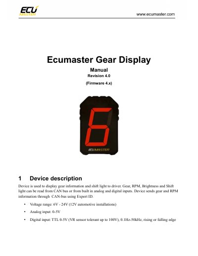
This manual explains how to configure the Ecumaster Gear Display Module 4.0 to display gear and RPM data via CAN bus or analog/digital inputs. It details settings for RPM and gear sources, shift light thresholds, brightness control, and export data formats. The module supports 6V–24V voltage, analog inputs 0–5V, and digital inputs up to 100V. Pinout and physical dimensions are also provided.
The manual includes examples for reading gear data from CAN ID 0x400 and configuring RPM from CAN or frequency inputs. It also covers shift light behavior based on RPM thresholds and brightness limits to prevent overheating.
| Voltage Range | 6V - 24V (12V automotive installations) |
|---|---|
| Analog Input | 0-5V |
| Digital Input | TTL 0-5V (VR sensor tolerant up to 100V), 0.1Hz-50kHz |
| Brightness Limit | Linearly limited from 100@40°C to 0@80°C |
The module supports 6V–24V, with 12V automotive installations as default.
Brightness is limited linearly from 100% at 40°C to 0% at 80°C for overheating protection.