
This document provides the sample circuit diagram for an MPU board compatible with the Bug Finder BF3000, showing ROM, RAM, power and reset connections.
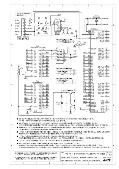
The manual presents a complete schematic for a sample MPU board designed to work with the Bug Finder BF3000. It details the connections for the KL5C80A 16 microcontroller, ROM and RAM memory, power supplies, and the Bug Finder connector.
Important notes include optional backup power for RAM, selectable memory types, and connector pin usage. The document also warns that the circuit is a sample only and that designers must verify details against component datasheets. This manual is written in Japanese.
| Microcontroller | KL5C80A 16 |
|---|---|
| Memory size | 128K Byte (1M Bit) ROM and RAM |
| Maximum crystal frequency | 20 MHz |
Both program memory (ROM) and data memory (RAM) are 128 KB (1 Mbit) each.
No, if RAM backup is not needed you can supply 5 V directly to the memory power pins.
A 6‑pin Japanese crimp terminal (EH connector) is used, compatible with the supplied cable.