
Wiring diagrams and connection details for the 大研工控 three‑axis glue dispensing control system.
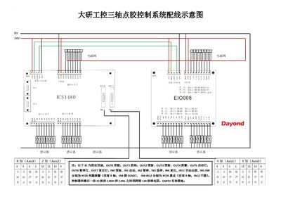
This document provides the complete wiring layout for the 大研工控 three‑axis glue dispensing control system, including axis assignments, I/O pin functions, and signal line conventions. It shows how to connect the controller, I/O expansion board, touch screen, and servo drives.
Key points cover CAN‑bus termination, power supply requirements, grounding practices, and safety precautions such as separating high‑voltage and signal wiring and using shielded cables for servo signals. This manual is written in Chinese.
| Servo driver supply voltage | 24V~48VDC |
|---|---|
| CAN bus termination resistor | 120 Ω |
| OUT0 function | Enable |
| OUT1 function | Glue gun |
| OUT4 function | Alarm |
The servo driver should be powered with 24 V to 48 V DC.
A 120 Ω resistor must be placed between CANH and CANL on the controller and the last I/O board.
OUT1 is assigned to the glue gun.