
Hardware manual for CRT IH42EV series integrated closed-loop stepper motors, covering specifications, installation, wiring, DIP settings and error codes.
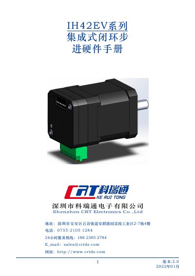
The IH42EV series combines a stepper motor and its drive in one unit. The manual introduces the product, safety instructions, drive parameters and model selection, mechanical installation, power supply and I/O wiring, DIP switch settings, communication parameters and error codes.
Models IH42EV04, IH42EV05 and IH42EV06 are listed with different body lengths, phase current, resistance, inductance, holding torque, rotor inertia and weight. The manual also lists connector pin functions, LED status indications and the USB-to-TTL cable. This manual is written in Chinese.
| Operating voltage | 8–50 VDC |
|---|---|
| Drive output current | 0.2–3.2 A |
| Output torque range | 0.2–0.6 N·m |
| Encoder feedback | 1000-line encoder |
| Communication method | TTL |
| Digital inputs | 2 inputs, 3.3–24 VDC high level |
| Digital output | 1 OC output, max 30 V / 30 mA |
| Maximum input frequency | 400 kHz |
| Recommended supply voltage | 36 VDC |
The manual states that the IH42EV has best performance at 36 VDC and allows an 8–50 VDC operating range.
The default baud rate is 115200, with 8 data bits, 1 stop bit and no parity.
Error codes are shown by combinations of red and green LED flashes; for example, one red and one green indicate drive overcurrent.
The two high-speed inputs accept 3.3–24 VDC high level directly and have a maximum frequency of 400 kHz.