
Chinese user manual for CNAOB AOB18 series digital panel voltmeters and ammeters: model code, technical parameters, programming, wiring and installation.
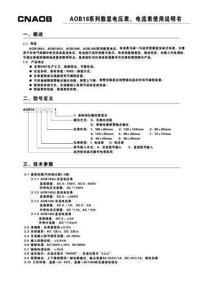
This is the Chinese user manual for the CNAOB AOB18 series digital panel voltmeters and ammeters, covering the AC models AOB184U and AOB184I and the DC models AOB185U and AOB185I. It describes the purpose of the meters, the model code, the technical parameters, front-panel programming, installation and wiring, precautions, and packing and storage.
The programming section explains the menu items set with the panel keys: the current transformer ratio (Ct), the decimal point position (dP), the range upper and lower limits (inPH and inPL), and, on versions with the relay alarm output option, the upper and lower alarm setpoints (AH, AL), the alarm hysteresis (dF) and the alarm output delay time (dt). Terminal layouts and wiring diagrams show direct, transformer and shunt connections, and the appendix gives worked programming examples. This manual is written in Chinese.
| Accuracy | ±0.5% of meter range |
|---|---|
| Sampling rate | AC 1 time/s, DC 2 times/s |
| AC input signal frequency range | 45–65 Hz |
| Auxiliary power supply | AC 220V ±10%, 50/60Hz |
| Input circuit power consumption | Less than 0.5 VA |
| AOB185U DC voltage range (direct measurement) | DC 0 to ±500 V |
| AOB185I DC current range (direct measurement) | DC 0 to ±5 A |
| Display | Single-row four-digit LED display |
| Alarm output contact capacity | AC 250V/1A, DC 30V/1A, resistive load |
| Storage temperature | Maximum +70 °C, minimum -40 °C |
Set Ct to the primary current divided by the secondary current of the external transformer. For a 200A/5A transformer Ct is set to 40; when no external transformer is used, Ct should be set to 1.
The POWER terminals take an AC 220V ±10%, 50/60Hz auxiliary supply. Other values must be stated when ordering.
The upper limit alarm AH is set as a percentage of the meter range: the value to be alarmed divided by the meter range times 100%. Setting AH to 120.1% turns the upper alarm off.
Cut the opening that matches the meter case size, insert the meter into the opening, put the two mounting accessories into the clamp slots of the housing and push them tight by hand.