
User manual for the CleanPowerAuto MiniBMS V3 battery management system, covering installation, operation, LED signals and wiring.
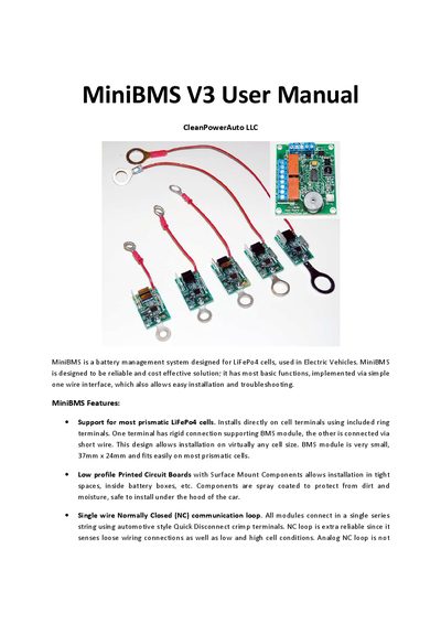
The MiniBMS V3 is a compact battery management system for LiFePo4 cells used in electric vehicles. It provides basic protection functions such as high‑voltage cutoff, low‑voltage cutoff, shunt balancing and a single‑wire normally‑closed communication loop. The module measures 37 mm × 24 mm and draws less than 4 mA in normal operation, dropping to 0.1 mA when the pack is idle.
The manual details step‑by‑step installation of cell modules, wiring of the NC loop, connection of the head‑end control board to the charger and motor controller, and explains the meaning of the red LED status patterns. It also includes wiring diagrams, safety warnings, and optional charger‑control options using an AC relay or charger‑integrated BMS input.
| Dimensions | 37 mm × 24 mm |
|---|---|
| Operating current (normal) | < 4 mA |
| Sleep (quiescent) current | 0.1 mA |
| Maximum shunt‑balancing current | 0.75 A |
| PTC fuse trip rating | 80 °C or 1 A |
| Low‑Voltage Cutoff (LVC) settings | 2.5 V @ 0 °C, 2.6 V @ 25 °C, 2.7 V @ 50 °C |
Manually disconnect one of the NC loop wires; the buzzer will sound after a 5‑second delay, confirming the alert function.
The B+ terminal must be connected directly to a 12 V auxiliary battery, and the ignition key input must be present to reset the BMS after each charge.