
User manual for the M03/04-d series explosion‑proof smart electric actuator covering installation, wiring, operation, safety and maintenance.
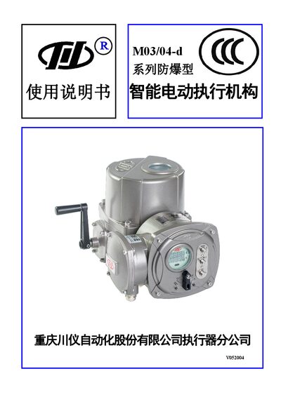
This manual provides a complete overview of the M03/04-d series explosion‑proof smart electric actuator, including its features, specifications, and typical applications in power, metallurgy, petrochemical and water‑treatment industries. It describes the internal structure, servo‑controlled motor, and the built‑in safety functions.
The document details step‑by‑step installation, external wiring, parameter setting, operation modes, fault diagnosis, safety precautions, routine maintenance, transportation, storage, and unpacking procedures, ensuring safe and reliable use of the actuator. This manual is written in Chinese.
| Input signal | 24 V DC or passive switch signals |
|---|---|
| Output signal | Four passive switch outputs (fault alarm, remote/local, fully open, fully close) |
| Positioning accuracy | ±1 % FS |
| Dead band | 0.4 %–10 % FS |
| Motor mode | S4 |
| Power supply | Three‑phase 380 V ±10 % 50 Hz or single‑phase 220 V ±10 % 50 Hz |
| Explosion protection level | ExdⅡBT4 |
| Operating temperature | -20 °C to 60 °C |
| Relative humidity | ≤95 % |
| Atmospheric pressure | 86 kPa to 106 kPa |
| Output torque (example model M0□11-d□100) | 28 Nm |
| Connection flange standard | ISO 5211 |
Power must be disconnected for at least 5 minutes, and the surrounding atmosphere must be free of flammable gases before opening the cover.
Use 1.0–1.5 mm² hard or flexible cable for power, and 0.25–1.0 mm² hard or flexible cable for signal lines.
The limit and torque switches are adjusted as described in section 3.5 of the manual; follow the illustrated procedure to set the desired positions.