
The C1 Multifunction CNC Board User Manual provides features, specifications, wiring instructions, and safety guidelines for the board.
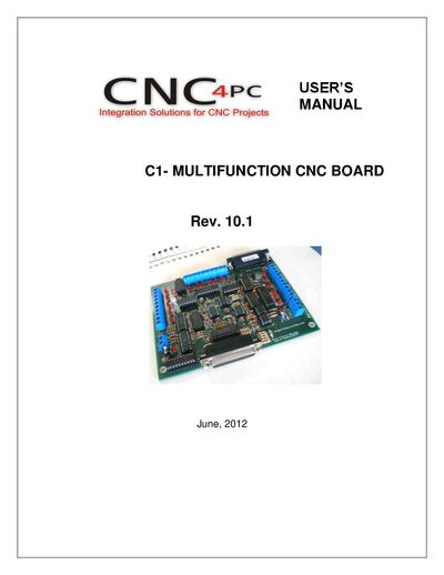
This manual describes the C1 Multifunction CNC Board, an IEEE 1284‑compatible device with optoisolated inputs and buffered outputs. It outlines the board’s features, such as pull‑up/down selection, status LEDs, and external enable control.
The document includes detailed wiring diagrams for switches, NPN/PNP sensors, and COM jumper settings, as well as specifications for digital inputs and outputs, dimensions, and safety warnings for CNC use.
| Number of digital inputs | 5 |
|---|---|
| Input on‑state voltage range | 2 to 5 V DC |
| Input maximum off‑state voltage | 0.8 V |
| Input typical signal delay | 2.8 µs |
| Number of digital outputs | 12 |
| Maximum output voltage | +0.5 V over 5 V supply |
| Typical output current | 24 mA |
| Output maximum off‑state voltage | 0.44 V |
| Maximum supported output frequency (pins 2‑9) | 1 MHz |
| Typical output signal delay | 3 µs |
The board must be provided with a 5 VDC signal to enable operation.
The board provides five digital inputs.
Each output can source a typical current of 24 mA.
Yes, it follows the IEEE 1284 standard for parallel‑port communication.